Table of Contents
Open Table of Contents
Introduction
So, while I was designing a power supply for my custom STM, I ran into a common problem - high inrush currents.
If you’ve ever heard of a loud ‘thump’ or noticed the lights flicker when turning on a high-powered amplifier or benchtop experiment, you’ve experienced inrush current. This momentary surge in current is due to switching on a device with a large transformer or big filter caps, where those components behave as short circuits momentarily:
The causes are dominated by transformer core saturation (severe when power is applied at the zero crossing of the AC waveform - the flux jumps into saturation because there is no opposing field to damp the ramp rate) and capacitive charging (filter caps on the secondary are discharged at startup and present a near short to bridge rectifier). Toroidal transformers (especially >300 VA) are notorious for very high magnetizing inrush; they can draw several hundred amperes for a few cycles if switched at the “wrong” instant. They can draw massive current (20-50 Amperes) for a brief instant, and this can blow fuses, stress transformer windings, damage and damage bridge rectifiers. Ooof, I found out the hard way.
Without mitigation, the startup inrush current is only limited by any ESR in the circuit (wiring, windings, etc.), which is usually low. Thus, fuses must be oversized (slow-blow types) just to survive turn-on, undermining their protection ability. Components also endure some mechanical and thermal shock. Soft-start circuits are recommended for large transformers (greater than 300 VA) and for any system with significant capacitive loading.
A soft-start circuit inserts a series impedance (power resistors or thermistors) to limit the current during the first 100-200 ms. Then, it bypasses the resistor after the initial surge using a relay or MOSFET, restoring full voltage and normal operation. Bypassing is important as to not dump power out unecessarily, making your system ineffcient. My implementation was inspired by Rod Elliott’s ESP Project 39.
Common Techniques Overview
NTC Thermistor
Use a Negative Temperature Coefficient (NTC) thermistor in series with the AC line. It has high resistance when cold (at startup) and then self-heats and drops to a low resistance during steady operation. This passive method automatically limits the surge and then “gets out of the way” (mostly) as current flows continuously.
Many consumer power supplies (PC ATX supplies, TV sets, etc.) use an NTC like the popular “CL-30” or “NTC 5D-11” at the AC input. At startup it might be ~10 Ω, but after a few seconds of 2–3 A flow, it heats up to <0.5 Ω. This simple component often prevents nuisance fuse blows at turn-on.
NTCs are simple and low cost, self adjusting, and compact, but they continuously dissapate power, and have a cool-down requirement (if the PS is turned on and off immediately, the NTC would still be hot). It typically takes 30-120s to cool down to be effective again. In addition, an NTC has some residual resistance at steady state, even while hot, whcih causes a continuous voltageg drop and heat. Also, inrush events stress the thermistor, which would cause them to degrade over time.
NTC thermistors generally fail open-circuit if overstressed (they might crack). An open failure would cut power entirely (which is safe, though the equipment won’t turn on). A worse scenario is if it fails short (rare for NTCs, but possible in extreme overload) – then it offers no inrush protection at next startup. Another subtle failure is aging: repeated heating cycles can shift the NTC’s resistance. If it becomes too low when cold (aging or if ambient is hotter), the inrush limiting effect is reduced.
In practice, NTC limiters are best for cost-sensitive and low-to-medium power devices where a slight efficiency loss is acceptable and the device isn’t frequently power-cycled. For instance, many amplifiers up to a certain size or TVs use NTCs since the convenience and cost outweigh the drawbacks. However, for very large transformers or mission-critical reliability, designers often look to more robust solutions (or they might use an NTC with a bypass relay, effectively combining techniques).
Series Resistor with Relay Bypass
Use a fixed power resistor in series with the line during startup, then after a short delay, short out the resistor with a relay to remove it from the circuit The resistor handles the surge (converting it to heat), and the relay then closes to allow normal operation with negligible added resistance.
Essentially, at turn-on the current flows through a high-power “ballast” resistor, typically chosen to allow a tolerable surge (e.g. 2× or 3× the normal current). After ~0.1–0.5 seconds, a relay closes to bypass the resistor, connecting the transformer directly to mains for normal operation. The relay is usually driven by a simple RC timing circuit or a small auxiliary circuit that detects the mains voltage.
A key design step is choosing the resistor value and power rating. Often the goal is to limit inrush to about 200% of full-load current (or a few times normal current). Using Ohm’s law, R = V_mains / I_limit. For example, Rod Elliott describes a 500 VA transformer (at 240 V, ~2 A normal) limited to 4 A peak (200%) would require ≈60 Ω series resistance. You could use a single 56–68 Ω resistor, but the instantaneous dissipation can be huge (on the order of 900 W in that 60 Ω during the first half-cycle).
Since the resistor only endures this for a brief 0.1–0.2 s, we can use a much smaller physical resistor if it can handle the energy pulse. Typically, designers use multiple resistors in series/parallel to achieve the needed value and share the surge energy. (Elliott’s example uses three 180 Ω 5 W resistors in parallel, giving 60 Ω combined). The trio can handle the surge together without Chernobyling.
The timing to activate the bypass relay is usually set around 100 ms, which is sufficient for roughly 5–6 AC cycles to pass and fill the transformer core and charge capacitors. In fact, about 100 ms is often cited as an optimum delay – long enough to tame inrush, but short enough that the transformer voltage is at full supply quickly thereafter (avoiding excessive warm-up time or output sag). Delays up to ~200 ms are usually fine as well.
Control circuit: The simplest control is an RC network driving a transistor or a dedicated timer (or even just the relay coil indirectly). For example, one can charge a capacitor via a resistor from a low-voltage source; when the voltage on the cap (after ~100 ms) exceeds a threshold, it drives a transistor that energizes the relay coil. Elliott’s original Project 39 design used a MOSFET’s gate threshold as a crude timing trigger, and later a more stable op-amp comparator in the PCB version. Often a diode is placed across the relay coil (for DC coils) to catch the inductive kick when de-energizing, and a bleeder resistor across the timing capacitor ensures the circuit resets when power is removed (so a quick off/on cycle will still insert the resistor again). As a refinement, Rod Elliott added a small transistor for snap-action: when the relay coil starts to pull in, this transistor quickly charges the timing cap, hastening the drive to fully engage the relay. This avoids the relay chattering or engaging too slowly.
The chief worry is if the relay never closes when it should. In that case, the series resistor(s) would remain in circuit continuously. They are not rated for continuous full-load operation, so they will overheat severely. A well-designed circuit will choose resistor values such that if this happens, either a protective fuse blows or the resistors themselves eventually fail open (hopefully without fire). As Rod Elliott warns, if the relay doesn’t operate, the resistors will rapidly overheat – hence the importance of using an appropriately sized resistor or multiple resistors and mounting them to withstand short-term overheating. Conversely, if the relay were to weld shut or close too early (before the inrush has subsided), the circuit effectively behaves as if there were no soft-start (or a prematurely bypassed one), defeating the purpose. Another scenario: if the mains is momentarily lost and comes back within a very short time, the relay might still be engaged (or the timing cap might not have fully discharged) so the resistor doesn’t get inserted on that re-application. This could cause a surprise surge. Designing the control to reset quickly helps; e.g. using a bleed resistor or a normally closed contact to discharge the cap on power-down. Lastly, consider a fault at startup (e.g. a shorted rectifier or capacitor). The soft-start will limit the current to, say, 200% of normal – which might prevent a fast fuse blow. In such a case, the circuit could sit with high current through the resistor for longer than intended. This is a tough failure mode; Elliott strongly suggests using a separate small transformer supply for the relay inrush circuit if possible, so that even under fault the relay can engage and not leave the resistor burning in circuit. In any case, designers should ensure that under fault, something (fuse or resistor acting as a fuse) will eventually protect the circuit.
Active MOSFET Limiting (Linear Ramp):
Use a transistor (MOSFET) as a series pass element that initially starts in a high-resistance state and is then gradually turned on (either passively via an RC on its gate or actively via a controller). This approach essentially provides an electronically controlled variable resistor that smoothly ramps the current or voltage to the load.
In DC applications (like connecting a large capacitive load to a battery or DC bus), MOSFET-based soft-start (often called “hot-swap controllers”) are very common. For AC mains applications, a MOSFET solution essentially functions like a solid-state relay (SSR) with soft-start capability. Because an AC MOSFET-SSR requires two MOSFETs (to block both polarities when off), the implementation is a bit more complex than DC, but the principle remains: control the devices’ conduction such that the current is limited to a set threshold or the voltage is slewed slowly.
Active MOSFET soft-start is very popular in DC power distribution (server backplanes, battery systems) – often implemented by specialized ICs that control a pass MOSFET and provide a current-limited startup (for instance, analog ICs from Linear Technology, TI, etc., for hot-swap controllers). In AC mains applications, MOSFET-based limiters have been used in some power conditioners and high-end amplifiers. One example is using a back-to-back MOSFET pair as a solid-state relay: initially, the gate is driven such that the MOSFETs are partially on, behaving like a resistor that limits current; after a short time, they are fully enhanced. A well-known design in DIY circles was published in AudioXpress (Jan 2005) using a MOSFET-based soft start with a PIC microcontroller and opto-drivers, which Rod Elliott references as an “inline inrush limiter” sound-au.com . That design (and others like it) demonstrates that with a microcontroller, one can orchestrate a MOSFET soft-start and even combine it with other duties (like power sequencing, etc.).
Triac/SCR Phase-Controlled Start
Use a triac or thyristors on the AC line to control the phase angle or timing of conduction for the first few AC cycles. For example, initially trigger the triac late in each half-cycle (allowing only a small slice of the AC waveform through), then progressively trigger earlier each cycle until full conduction. Alternatively, a triac (or pair of SCRs) can be used to connect the load at an optimal point in the AC wave (e.g. at peak) to minimize the surge, or even to implement a “controlled bridge” that actively regulates inrush current.
A triac is a bidirectional AC switch (essentially two SCRs back-to-back) that can be triggered at any phase angle of the AC waveform. Using a triac (or pair of SCRs) for soft-start involves controlling when in each AC half-cycle the device is triggered. Two common strategies are
- Phase Angle Ramp: Start by triggering the triac late in each half-cycle (for example, at 120° out of 180° – meaning only a small slice of the AC sine wave near the end gets through to the transformer). This limits the effective RMS voltage delivered to the transformer initially, thus limiting current. Then over successive cycles, the trigger point is advanced closer to the zero-crossing, gradually increasing the portion of the AC waveform that passes. After a short period (maybe a few cycles to a few hundred ms), the triac is triggered at or near 0° (essentially fully on for the entire waveform), and the soft-start is complete. This is analogous to a dimmer circuit that slowly brings up a lamp’s brightness – here we bring up the transformer’s input voltage gradually.
- Synchronized Switching (peak switching): Another approach is to choose the optimal moment to initially energize the transformer. As mentioned earlier, energizing at the AC peak results in the least magnetizing inrush for a transformer. One could design a circuit that, when you hit the “On” switch, waits until the mains sine wave is at its peak and then triggers an SCR at that moment. This doesn’t “ramp” the voltage, but it avoids the worst-case core saturation scenario (which occurs at a zero-cross turn-on). Some soft-start controllers do exactly this: they enforce that turn-on always occurs at a voltage peak. However, note that while this mitigates the magnetization surge, it doesn’t on its own limit the capacitor charging surge – inrush to caps is actually worst at peak as well (since that’s when the rectifier conducts). So peak-switching alone might be insufficient if large capacitors are present downstream. Therefore, one often combines peak switching with either some series impedance or a brief phase angle limit to handle caps.
- Burst limiting: A less common technique uses an SCR pair to effectively connect the load for one half-cycle, then skip a cycle, etc., in a controlled manner to limit average energy. However, this can cause DC bias in the transformer or significant flicker and is generally not used except in some motor soft-starts. For our purposes, the phase angle method is the typical triac soft-start strategy.
A triac-based soft-start usually requires a small triggering circuit. This could be analog (for example, an RC timer feeding a DIAC or a unijunction transistor circuit that gradually changes phase – similar to how lamp dimmers work but with a time-varying reference) or digital (a microcontroller or a dedicated ASIC that ramps the firing angle). The main pros are that there is no series resistor after startup, no mechanical components, and we can tailor the voltage ramp profile. In addition, there is a built in zero cross behavior (if designed to trigger at a certain angle every cycle).
The main cons are that a triac soft-start often benefits from a MCU for precise timing. This adds some complexity on a level similar to the MOSFET approach. Also, unlike a relay, a triac will always drop about 1V (depending on device and current), and will need a heatsink for high currents. The phase control is effectively voltage limiting - but doesn’t really regulate teh current. The actual current drawn by load depends on load’s impedance and inrush characteristics. nt drawn by load depends on load’s impedance and inrush characteristics.
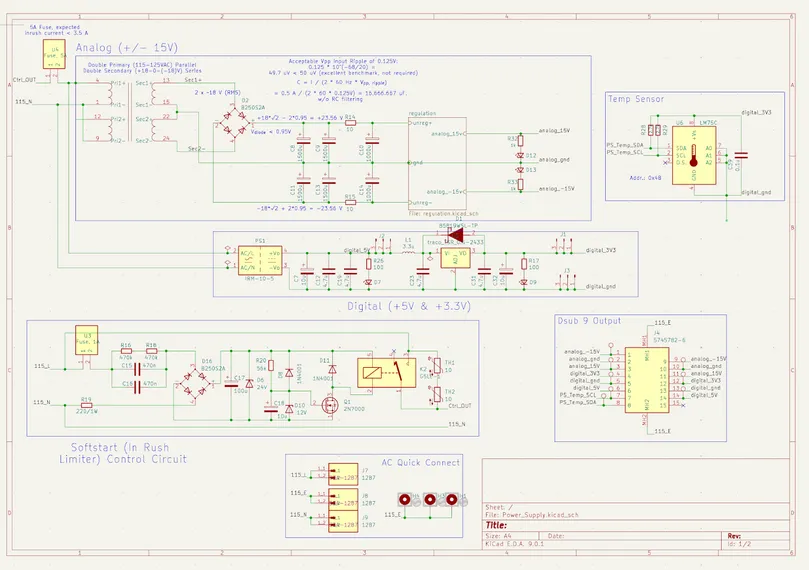
My Soft-Start Implementation
I chose to go with the NTC + Relay Hybrid soft-start, mainly due to it being relatively cheaper and about as efficient as the other methods suggested above.