Table of Contents
Open Table of Contents
Description
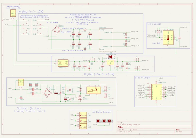
The power supply board distributes regulated voltages to analog and digital subsystems while incorporating protections, thermal monitoring, and status indicators to ensure safe, reliable operation. The board is designed to convert 115VAC mains into three isolated outputs: $15V analog rails, +5V digital, and +3.3V logic, each with specific regulators and filtering tailored to their respective noise and load sensitivity requirements.
Input Stage and Protection Circuitry
The board accepts standard 115VAC input through quick-connect terminals (J7—J9) and immediately applies robust protection mechanisms. Two fuses (U3, U4) segment the analog and digital paths: a 5A fuse safeguards the high-current analog transformer primary, while a 1A fuse protects the digital supplies and soft-start controller. These fuses isolate faults and limit catastrophic failure in the event of downstream shorts.
To manage inrush current—a common concern when powering systems with large electrolytic capacitors—the design employs two 10 NTC thermistors (TH1, TH2) in series with the AC line. At startup, these thermistors present high resistance, throttling the current spike as filter capacitors charge. As they self-heat, their resistance drops exponentially, minimizing steady-state power loss. To eliminate this inherent power dissipation altogether after initialization, a relay (K2) bypasses the thermistors via a timed control circuit.
This soft-start relay is driven by a discrete analog controller comprising an RC timing network (R16/R18 and C15/C16), a bridge rectifier (D16), and clamping circuitry using Zener and protection diodes (D6, D10, D11). Once the RC voltage exceeds the gate threshold of a 2N7000 N-channel MOSFET (Q1), the transistor switches on, energizing the relay coil. The relay closes, shorting out the thermistors and allowing the board to transition to full-power operation without inrush mitigation losses. This staged startup approach balances both longevity and energy efficiency.
Analog Rails (15V)
The analog section is powered by a custom-wound center-tapped transformer with dual 18VAC secondaries connected in series to generate 18VAC. The transformer primaries are wired in parallel for 115V operation, consistent with North American mains. A B250S2A bridge rectifier converts the AC waveform into dual-polarity DC voltages. Each output undergoes smoothing via RC filtering: 15,000F and 10,000F electrolytics in each rail, with 10 series resistors suppressing ripple and improving stability under load.
The raw voltages, approximately 23.6V DC after rectification, are regulated down to 15V using linear regulators. These regulators—TPS7A4700 and the TPS7A3301—provide low-noise, high-linearity outputs essential for analog front-end circuits such as the tunneling amplifier. While less efficient than switching regulators, linear regulators offer superior power supply rejection ratio (PSRR) and lower electromagnetic interference (EMI), critical for high-impedance measurements in our system. We simulated the power supply on LTSpice, and verified that our voltage peak-to-peak ripples are acceptable.
Indicator LEDs, powered directly from each 15V rail with series resistors, offer an effective visual verification of rail health.
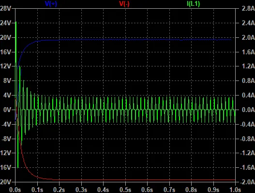
Model of Power Supply in LT SPICE (unregulated)
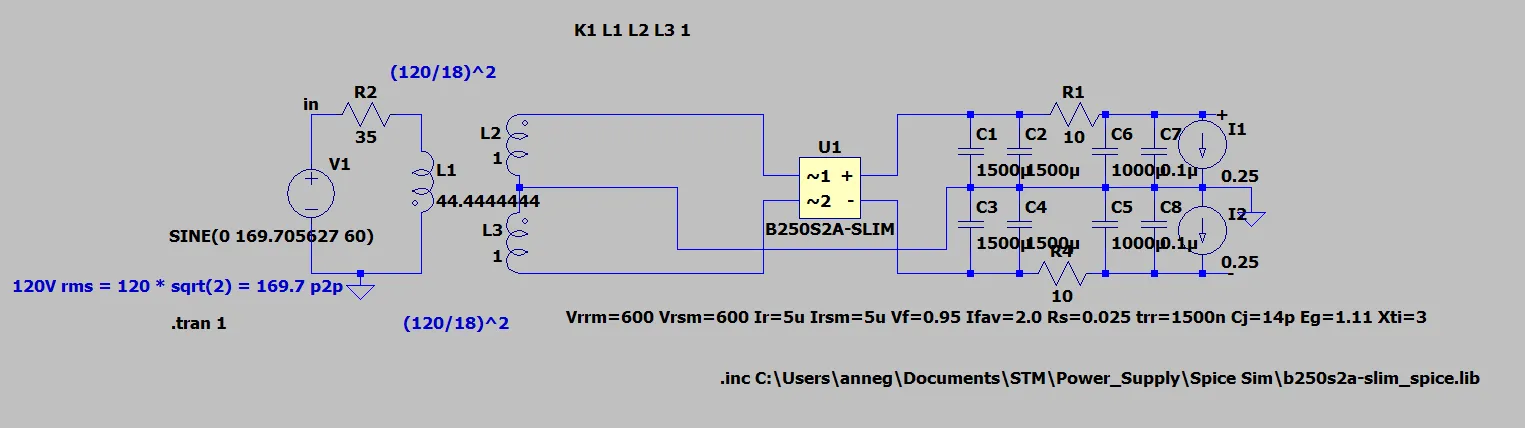 Plot of Inrush and Outputs of Unregulated Power Supply
Digital +5V and +3.3V Rails
The +5V digital rail is produced using an IRM-10-5 enclosed AC—DC switching module. This commercial power module integrates rectification, switching, and regulation in a compact, PCB-mountable package compliant with IEC safety standards. Its regulated output is filtered with a 100F aluminum electrolytic and 0.1F ceramic to ensure transient suppression across a wide frequency range.
A downstream TSR-0.5-2433 step-down DC—DC converter further reduces +5V to +3.3V. This switching buck regulator achieves high efficiency (90%) even at modest currents (500mA), making it well-suited for low-power digital subsystems such as microcontrollers, sensors, and communication ICs. Both its input and output lines are buffered with 100F bulk and 0.1F ceramic capacitors, forming a low-ESR decoupling network that suppresses noise coupling and high-frequency artifacts. Each digital rail is monitored by a status LED in series with a 100 resistor for quick diagnostics.
Monitoring and Output Interface
The board includes a digital temperature sensor (LM75C) powered by the +3.3V rail. This I\textsuperscript{2}C-based IC provides remote thermal monitoring with a resolution of 0.125\textdegree{}C and integrates neatly into the system controller via the J4 connector. The sensor’s I\textsuperscript{2}C lines (SDA/SCL), address select pins (R28/R29), and power/ground are routed through J4, enabling remote reading of power board temperature—a useful diagnostic during prolonged STM operation or debugging regulator thermal performance.
The D-Sub-9 connector (J4) is the main power interface, delivering 15V, +5V, +3.3V, analog/digital ground, and I\textsuperscript{2}C lines to the STM’s mainboard. This connector simplifies integration by combining power and control into a single shielded bundle.
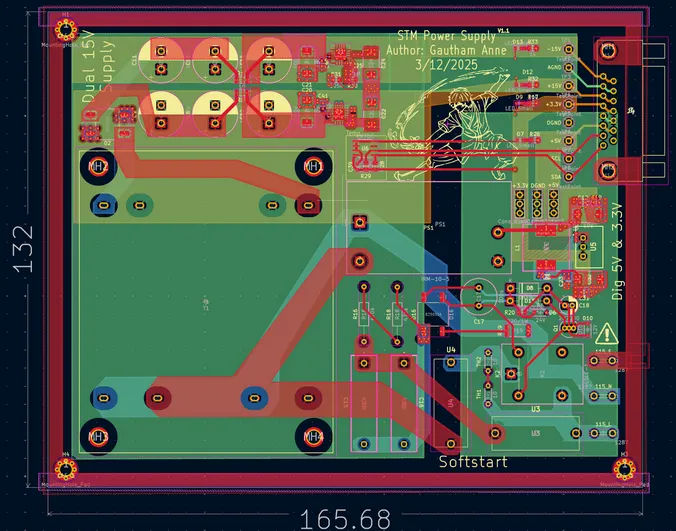
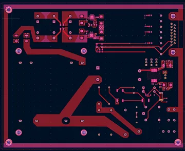
Layout and Safety Features
On the PCB, a red copper pour represents the earth ground plane, carefully routed to avoid coupling between analog and digital returns. Regions of the silkscreen are intentionally removed—especially around mounting holes and edge clearance zones—since certain inks can become marginally conductive under high humidity or contact with grounded metal enclosures. Omitting silkscreen at mechanical interfaces ensures safe discharge paths directly to chassis ground and avoids inadvertent shorts from conductive enclosure contact.
Copper Trace Spacing (conservative for HV safety standards).
Spacing and clearance around high-voltage traces follow IPC-2221B standards. These design rules dictate minimum air and creepage distances based on voltage class, ensuring safe isolation between live mains and low-voltage control circuitry. While EMI and ground-loop issues are not critical in this low-frequency analog supply, attention to these safety details enhances system robustness and regulatory compliance.