Table of Contents
Open Table of Contents
Description
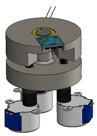
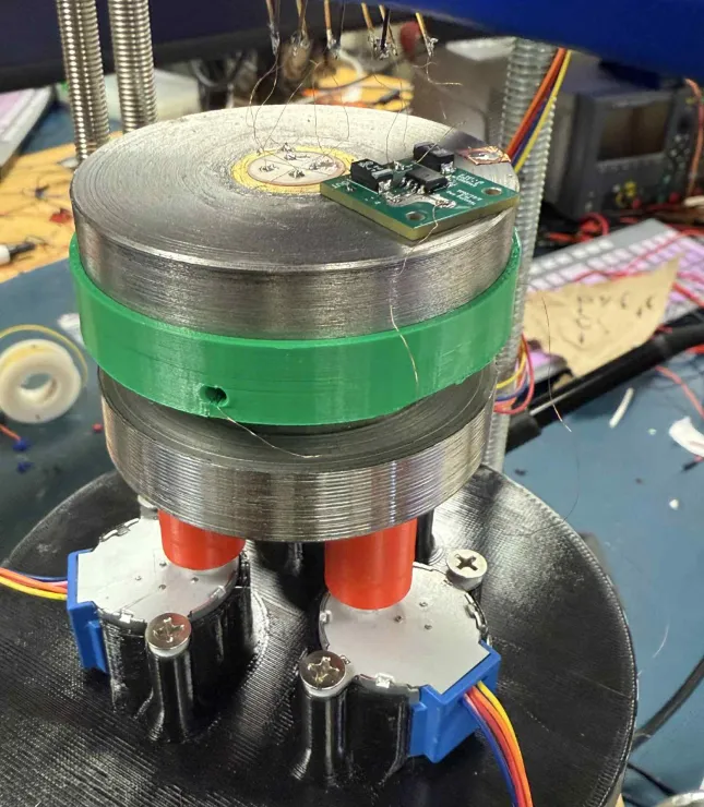
The scan head is the heart of the STM, designed for maximum rigidity, thermal stability, and kinematic symmetry to ensure nanometer-scale positioning with minimal drift and vibration sensitivity. Our scan head features a compact circular architecture, machined from steel to exploit its high stiffness. Fabrication was performed in the Ford Prototyping Lab using a combination of manual turning, CNC milling, and vertical milling. This hybrid manufacturing approach enabled us to achieve dimensional tolerances within thou, ensuring coaxial alignment between the piezo actuator, tip, and sample. Here is a model and the actual implementation of the scan head:
Mechanical Grounding and Amplifier Isolation
Although steel is not an electrical insulator, it was chosen for its mechanical stability. To prevent unwanted leakage currents or ground loops—which could corrupt femtoampere-level tunneling signals—we isolated the tunneling preamplifier from the scan head using a 3D-printed dielectric mount. The amplifier’s ground plane is tied to a separate analog reference potential, and all high-impedance inputs are shielded with a driven guard strategy. By physically decoupling mechanical and electrical ground domains, we reduce susceptibility to EMI and leakage-induced drift.
Fine Positioning via Quadrant Piezo Unimorph
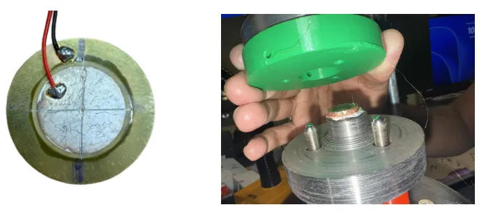
Sub-nanometer precision in the lateral and vertical directions is provided by a piezoelectric unimorph disk actuator segmented into four independent quadrants. The disk, fabricated from lead zirconate titanate (PZT), bends in response to an applied electric field via the inverse piezoelectric effect. We actually decided to use the common guitar pickups, since their relatively high resonance peak (6.3 kHz) allowed us to operate in ‘rigid’ regimes. Let be the transverse piezoelectric strain coefficient. Then the radius of curvature of the bending disk is related to the applied voltage as:
where is the thickness of the piezo layer. Displacement at the center is approximately:
where is the disk radius. With quadrant voltages to , the differential bending between quadrants induces motion in the , , and directions according to:
To extend vertical displacement and reduce parasitic capacitance near the tunneling junction, a ceramic standoff was super glue to the disk center. This standoff:
- Amplifies horizontal motion mechanically via leverage,
- Electrically isolates the tip from piezo electrodes,
- Minimizes thermal drift due to similar thermal expansion coefficient to the piezo material.
The STM tip is mounted at the free end of this standoff, ensuring that all mechanical and electrical motion originates from a single, rigid reference point within the scanner assembly.
Symmetry and Modal Considerations
The radial symmetry of both coarse and fine positioning subsystems ensures minimal coupling between orthogonal motion directions. The compact circular geometry also minimizes mechanical moment arms and higher-order vibration modes, improving rejection of external disturbances.
Example of cut piezo (left), and mounted sample (right)