Table of Contents
Open Table of Contents
Introduction
This post is a writeup of my final report for my CAD/CAM manufacturing course I took this past winter quarter. The course focues on the translation of a part from design to manufacturing at scale, with an emphasis on injection molding techniques, specifically for plastic parts. Using NX, my groupmates (Alazar Tegegnework, Innocentia Eweyeju) and I designed a bar soap holder (CAD), named Soaporter, and generated toolpaths (CAM) to machine our molds out of aluminum. Afterwards, we characterized our injection molded parts and examined them for any defects. If you’d like a pdf version of our report, see below.
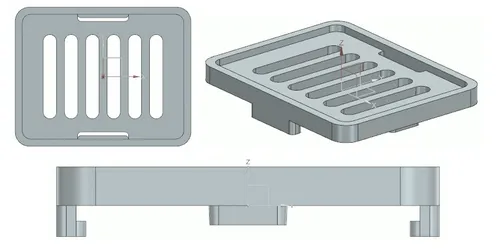
Bar soap has a conventional reputation for accumulating bacteria due to its surface-based usage rather than free-handed pour like that of body wash. As a result, our design is composed of two parts: a lid with ventilation grooves for soap-drying post-use, and a base where excess water can be caught and disposed of by the user. Our initial snap fit design was inspired by the battery holder of a remote, making it easy for the user to remove the lid from the base with just one hand.
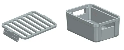 Early Design of Soaporter
This design looked very promising until the CAM stage, where it became impossible and time consuming trying to make this design manufacturable. Due to the challenges faced, the design was changed to be a lot simpler to be cantilever-based snap-fit closure. In this design two snaps from beneath the lid enclose two tabs extruded from the top of the base.
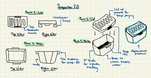 Rough sketch of initial product ideation
The development of our product included initial ideation, sketching, reiterative CAD modeling, mold modeling, machining, injection molding and lastly metrology and part analysis. Each stage played a crucial role in creating a reliable plastic design. Though the CAD renderings of our initial concept are accurate relative to the early sketches (see Figure 3 below), the ultimate dimensions of each part were carefully chosen given the design restrictions of the assignment, the sizes of the mold blanks to be used in CNC machining, and the geometry needed for injection molding processes. This report delves into the design process of our final product.
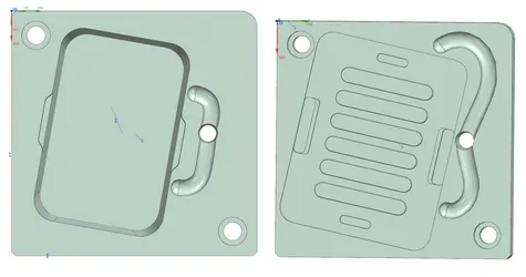
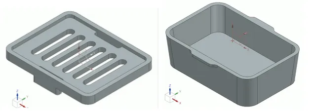 The part model’s lid (left) and base/base (right).
Part Design
Design for Manufacturing
As mentioned in the earlier section this design is a lot simpler from our original design to help simplify the manufacturing challenges. Since the final part will be injection molded, design for manufacturing means, both designing a manufacturable mold and an injection moldable part for both the lid and the base.
Base Desgin
Manufacturability of the base was the biggest challenge in the earlier design, causing the need to pivot. Therefore, the design of the base is very simple as shown in Figure 3. The walls have a uniform 0.1 inch thickness with a large 5 degree draft for ease of ejection from the molding machine. The edges have a 0.25 inch radius fillet, to allow for using one tool (0.5 inch EM) to create the outline of the mold. The lip required for the lid to snap fit into the base is a simple outward extrusion from the two sides of the base. This base design was a lot easier to create a manufacturing process and as will be discussed later made machining very easy.
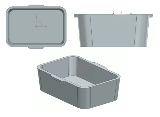 Base CAD design.
Lid Design
Similarly to the base design, the lid incorporates 3 degree draft holes for ease of removal from the injection molding machine. To help decrease the number of tools and operations used to make this part, the holes are 0.25 inch in diameter with a 0.125 inch gap between these holes. This design allows us to do simple operations with a ¼ and ⅛ end mills and ball mills to manufacture our molds. In order to avoid having undercuts we created 0.125 inch holes on the side of the part as shown in Figure 5. Lastly, the Lid has a uniform wall thickness of 0.15 inches to help simplify the injection molding process.
Lid CAD design
Design for Assembly
Given the complexity of our design in terms of finding feasible parting lines, adding functionality and accommodating for a part with taller walls, we ultimately prioritized simplicity for the snap-fit mechanism of our product. Utilizing a cantilever-type snap-fit closure, extruded snaps from beneath the lid component of our overall part experience an applied force as the part is pushed down onto the top of the base, enclosing the base’s tabs made to support the snaps. Since we chose a higher wall thickness, tapering our lid’s cantilever snaps was unnecessary since the “beams’” thickness was sufficient structural support to ensure durability over the course of the product’s use.
Mold Design
Layout
When creating the molds for the base and lid, we placed our parts at an angle nearly diagonal to the blank to maximize the size of the soaporter, while still having ample room for runner systems. We made sure not to interfere with the holes designed on the blanks for bolting and mounting the mold halves during injection molding. Our runners extended in two different directions for both the base and lid to maximize material flow while also promoting uniformity as the molten plastic filled the geometry during injection molding. Our sprue was placed between the runner such that material could flow through it into both directions of the runner rather than from one far end of the runner, traveling a longer distance during infill. Our gates on the base mold were placed at two points along its right wall, and the gates on our lid mold were placed at its top edge and right wall beneath its right snap fixture.
Cavities of base part (left) and lid part (right).
Manufacturing Process
CAM Operation Overview
To prepare for injection molding, we machined a cavity and a core for both the lid and base parts of the soaporter. Utilizing CNC to do so, a series of CAM operations constructed in NX were utilized. Each method, tool and purpose of the individual operations is detailed here.
Table 1. Core Mold for Lid (1 hour 33 min)
| Process | Method | Tool | Discussion |
|---|---|---|---|
3D Adaptive Roughing 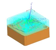 | MILL_ROUGH | EM 0.5 | Removes sufficient material from stock |
3D Adaptive Roughing 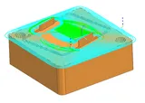 | MILL_SEMI-ROUGH | EM 0.5 | Helps flatten the remaining part left from roughing |
Cavity Mill 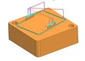 | MILL_FINISH | EM 0.125 | Creates the perimeter core for the walls of the lid |
Table 2. Cavity Mold for Lid (1 hour 14 minutes)
| Process | Method | Tool | Discussion |
|---|---|---|---|
Cavity Mill 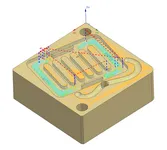 | MILL_ROUGH | EM 0.25 | Removes sufficient material from stock |
Cavity Mill 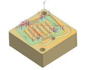 | MILL_FINISH | EM 0.25 | Creates a good surface finish for the face of the lid |
Cavity Mill 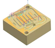 | MILL_ROUGH | EM 0.125 | Removes significant material around the lid’s snap fixtures |
Cavity Mill 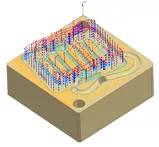 | MILL_FINISH | BM 0.125 | Creates a good surface finish on the face of the lid near and in between the ventilating grooves |
Cavity Mill 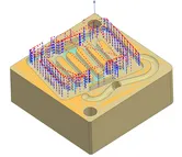 | MILL_FINISH | EM 0.125 | Creates a better surface finish on the face of the lid near the grooves |
Cavity Mill 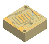 | MILL_FINISH | EM 0.125 | Removes small material around the lid’s supporting tabs |
Cavity Mill 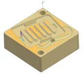 | MILL_FINISH | EM 0.125 | Removes small material around the lid’s supporting tabs |
Planar Mill 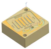 | MILL_FINISH | BM 0.25 | Removes material to create the runner for the lid’s mold |
Table 3. Core Mold for Base (1 hour 17 min)
| Process | Method | Tool | Discussion |
|---|---|---|---|
3D Adaptive Roughing 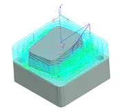 | MILL_ROUGH | EM 0.5 | Removes sufficient material from stock |
Cavity Mill 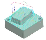 | MILL_FINISH | EM 0.5 | Creates the critical geometry for the base’s core |
Cavity Mill 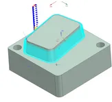 | MILL_FINISH | BM 0.25 | Creates a good surface finish for the base’s core |
Table 4. Cavity Mold for Base (1 hour 7 minutes)
| Process | Method | Tool | Discussion |
|---|---|---|---|
Planar Mill 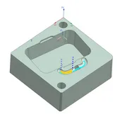 | MILL_FINISH | BM 0.25 | Removes material to create the runner for the base’s mold |
3D Adaptive Roughing 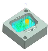 | MILL_ROUGH | EM 0.5 | Removes sufficient material from stock and creates the basic interior of the base |
Cavity Mill 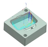 | MILL_FINISH | EM 0.5 | Creates a preliminary surface finish for the interior body of the base |
Cavity Mill 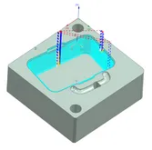 | MILL_FINISH | BM 0.125 | Creates a better surface finish and draft for the inner walls of the base |
Cavity Mill 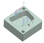 | MILL_FINISH | EM 0.125 | Removes material to create the tab supports for the snap-fit mechanism |
Cavity Mill 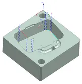 | MILL_FINISH | EM 0.125 | Finishing operation to smooth out bottom edges of the interior of the base |
CAM Process Review
Mold Operations
Core Mold for Lid. (Machine time: 1hr 33min) Our lid’s core operations consisted of only three methods, including mill roughing, mill semi-roughing and mill finish. There were only a few features created during this step as the lid’s more complex features were accounted for in its cavity half of the mold due to the placement of our parting line. Here, the lid’s snap extrusions and general body were accounted for as the mill roughing operation removed a significant amount of material from the blank to create the critical size of the lid, and a finishing operation accounted for its snaps.
Cavity Mold for Lid.(Machine time: 1hr 14 min) Our lid’s cavity operations primarily consisted of mill finishing methods between end mills and ball mills to create finer geometry for this part. The lid’s ventilating grooves possessed both straight lines and rounded edges with very little space between each groove. Therefore, a mill finishing operation was able to take the role of a mill roughing one to remove this very little, precise material in between curves. Some mill roughing was still utilized to remove less critical material from the area of the face of the lid around the group of grooves. In the same light, the small pockets of material where the lid’s supporting tabs would be injection molded were also taken care of using finishing operations rather than roughing since there wasn’t much material to be removed from those portions of the stock. After material removal, a series of additional finishing operations here were conducted for the purpose of a good surface finish.
Core Mold for base. (Machine time: 1hr 17 min) Our base’s core operations were also very minimal, consisting of only roughing and finishing methods for a total of three operations. Much material was initially removed from the stock to get the general size and shape of the base, then finishing operations took care of refining the base’s shape and draft for injection molding, along with its surface finish.
Cavity Mold for base. (Machine time: 1hr 7 min) Given the simpler geometry of the base, less operations were needed for its cavity when compared against the cavity of our lid. But similarly, more finishing methods were used as opposed to roughing. Roughing operations were still essential for removing much material from the stock to create the general interior and depth of the base body. Finishing operations then ensured a good surface finish within that interior along the walls of the base. Finishing operations also removed material from smaller pockets of the part such as the runner and tabs to support the lid’s extruded snap fixtures for assembly.
Process Modifications
During machining and molding, several unexpected issues required modifications to our original CAM strategy and mold assumptions.
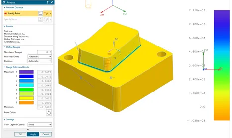
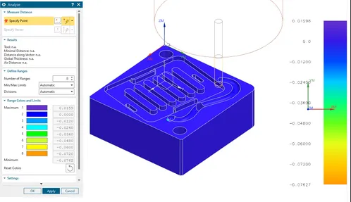
One of the most noticeable outcomes was the “stepped” appearance along the drafted walls of the molds, particularly visible in the base core. In CAD, the 5o draft appeared smooth and continuous (Figure 7).
 CAM operation analysis of our base core.
However, during machining, the drafted faces were approximated by discrete tool passes, and because we use relatively large stepovers and limited the number of finishing passes to reduce machining time, the toolpath left visible markings along the angled walls (Figure 8). This effect was amplified by the relatively steep draft angle. While 5o improves ejectability for injection molding, it also increases the vertical change per radial tool increment. As a result, each Z-level pass created a small but visible ledge, which affected the mold surface quality as well as the cosmetic finish of the molded base core walls.
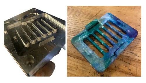
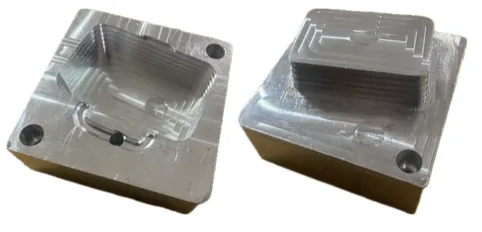 Cavity and core of base part.
Another significant issue that occurred during the machining of the lid core was when the ⅛” end mill fractured mid planar mill operation (Figure 9). This operation was responsible for cutting out the ‘lip’ of our lid. The breakage likely resulted from a combination of high tool engagement when starting the cut. Because the tool failed mid cycle, we had to revise our CAM. We regenerated the toolpath and reuploaded the G-code, ensuring proper tool-length offset commands (correct H___ offset commands) were included, which was necessary to re-establish the correct Z-referencing and prevent further crashes or dimensional errors. The restart process also required re-zeroing the tool offset of the ⅛” end mill. Although we successfully completed the core after the correction, the interruption increased machining time and introduced a small local surface inconsistency where the original tool broke.
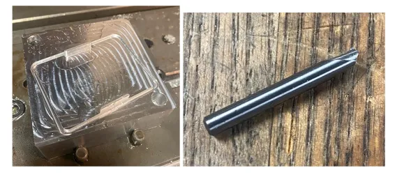 Core and tool of our lid part.
Another process modification arose from the surface finish of the lid cavity. Despite the CAD model showing a smooth base surface (Figure 10), the machined cavity exhibited small irregularities that transferred directly to the molded lid parts (Figure 11). The molded lids displayed minor waviness on the surface, but this was consistent across molded parts. The defect is most likely attributable to machining setups rather than CAM error. If we had to redo our machining, we would reduce the step over, decrease feed rate, and add another planar pass (perhaps with a varying toolpath profile) to improve surface smoothness. However, we also note that the surface texture could actually provide a ‘grippy’ texture for use in the bathroom.
 CAM operation analysis of our lid cavity.
 Cavity and injection mold of our lid part
Injection Molding
Molding Parameters
To get working injection molding parameters, some preliminary parameters were arbitrarily chosen and run on the mold. These values were:
- Injection Time: 4 seconds
- Pilot valve pressure: 8 PSI
- Barrel Temperature: 425 F
- Nozzle Temperature: 385 F
- Cooling Time: 1 Min
These parameters led to a lot of short shots, which gave a good reason to increase the injection time to 6-7 seconds, the valve pressure to 10 PSI, the barrel temperature to 450 F and the nozzle temperature to 390 F. These parameters also led to a harder time removing part form the mold which caused the change of the cooling time to 15 seconds. The final parameters are shown below.
Table 5. Molding Parameters for base and Lid
| Parameter | Value |
|---|---|
| Injection Time | 6 seconds |
| Valve Pressure | 10 PSI |
| Barrel Temperature | 450 °F |
| Nozzle Temperature | 390 °F |
| Cooling Time | 15 seconds |
The barrel temperature and nozzle temperature are a little out of the ordinary, as the machine itself recommends Barrel temperature of 425 F and Nozzle temperature of 450 F for PolyPropylene. This would have been the temperature we would have set but the injection molding machine was not going above ~395 F for the Nozzle temperature, no matter the temperature we set the machine to. This ended up causing a little problems since as part of this project we were trying to injection mold 20 of each part. After doing 2-3 injections, the nozzle will cool down to ~387 F which at that point starts to cause short shots again. The only solution we found was simply waiting for the machine to go back up to around ~390 F before injection molding again.
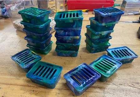 Assembling Soaporters is very simple. The first step is to latch one side of the lid onto the base, then snap in the other side.
Metrology
Once injection molding was complete, we conducted a series of measurements on chosen dimensions of our lid and base part to conduct some part analysis of its defects (such as shrinkage) and how closely our tolerance matched any dimensional deviation post-production. For the base part, we chose to measure the maximum distance between its two shorter inner walls that possess no unique geometry that could skew our data, such as the base’s extruded tab supports made for the snap-fit. For the lid part, we chose to measure the maximum distance between the outer walls of its simple extruded supports made for a slight interference fit with the base when close, snapped and assembled onto it. We chose this dimension for simplicity as well and accurate data collection since the lid possesses several unique features that could interfere with our calculated standard deviation–inlcuding the grooves and the extruded snaps made for assembly.
Selected Geometry and Specified Tolerance
To specify a tolerance for the base part, we researched the standard shrinkage for polypropylene by part size, and took a tolerance ~20% of that empirical shrinkage range for our given base’s dimension (see Figure 10). We conducted the same procedure for specifying the tolerance of the highlighted dimension on the lid (see FIgure 11) as well.
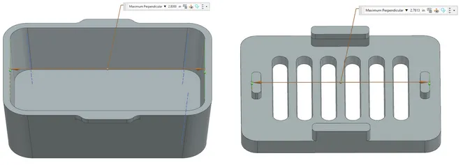 Selected geometry of base (left) and lid (right) parts.
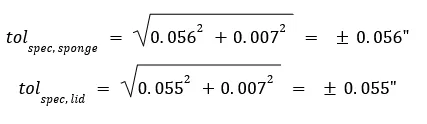
The typical shrinkage range for polypropylene is 1.0%-2.5%. Since we have higher wall thicknesses near the walls measured across for the base’s selected geometry, and higher feature thickness for the extrudes measured across for the lid’s selected geometry, we selected a higher shrinkage within this range to account for sink mark defects due to feature thickness of 2.0%. For the base, since the chosen dimension is 2.800”, our new dimension accounting for shrinkage is approximately (100%-2%)2.800” = 2.744”. The specified tolerance becomes ±(2.800”-2.744”), or about ±0.056”. Following suit for the lid’s dimension of 2.761”, the specified tolerance becomes ±{2.761” - [(100%-2%)*2.761”]}, or, ±0.055” for shrinkage factors alone. To further support a calculated specified tolerance, we considered the commercial tolerance of polypropylene (PP) by feature size. For the base’s dimension of 2.800” or ~71mm, the commercial tolerance for PP is ±0.170mm (for features between 21mm-100mm), or ±0.007”. Since the lid’s dimension is within the same feature size range, it also possesses a commercial tolerance of ±0.007”. To find a reasonable tolerance given these findings, we normalized each bilateral tolerance. For the base and lid, the overall specified tolerance was found as follows:
 Upon specifying these tolerances, we then compared them against the standard deviations found from our metrology measurements to ensure the differences are reasonable for polypropylene shrinkage standards.
Run Data
Utilizing the specified tolerances calculated from shrinkage factors and commercial standards of polypropylene, we set an upper and lower specification limit (USL/LSL) for the measurements of both the base and lid parts. For the base, our USL was found to be 2.800” + 0.056” = 2.856”, and our LSL was 2.800” - 0.056” = 2.744”. For the lid, our USL was found to be 2.761” + 0.055” = 2.816”, and our LSL was 2.761” - 0.055” = 2.706”.
Table 6. Metrology Measurements for Base and Lid
| Part | Base Measurements (in) | Lid Measurements (in) |
|---|---|---|
| 1 | 2.7035 | 2.6895 |
| 2 | 2.7075 | 2.7335 |
| 3 | 2.6835 | 2.7215 |
| 4 | 2.7100 | 2.7000 |
| 5 | 2.7100 | 2.6940 |
| 6 | 2.7175 | 2.6945 |
| 7 | 2.7105 | 2.7045 |
| 8 | 2.7050 | 2.6995 |
| 9 | 2.7105 | 2.7185 |
| 10 | 2.7055 | 2.6875 |
| 11 | 2.7115 | 2.7290 |
| 12 | 2.7145 | 2.7130 |
| 13 | 2.7210 | 2.7025 |
| 14 | 2.6690 | 2.6835 |
| 15 | 2.7075 | 2.7150 |
| 16 | 2.7190 | 2.7155 |
| 17 | 2.7185 | 2.7180 |
| 18 | 2.7160 | 2.7270 |
| 19 | 2.7170 | 2.7185 |
| 20 | 2.7210 | 2.6805 |
| Average | 2.7089 | 2.7073 |
| Std. Dev. | 0.0126 | 0.0158 |
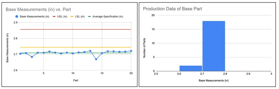 Base measurements for each part.
For the base, the specified measurements didn’t fall within the necessary upper and lower limits for this design. This is likely due to the larger wall thickness and height of the base promoting shrinkage due to a longer cooling time stemming from the geometry.
Base measurements for each part.
For the base, the specified measurements didn’t fall within the necessary upper and lower limits for this design. This is likely due to the larger wall thickness and height of the base promoting shrinkage due to a longer cooling time stemming from the geometry.
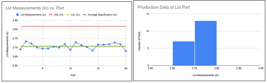 Lid measurements for each part.
Approximately half of the lid’s measurements fell within the upper and lower specifications, with the other half falling below the lower specification. This is also caused by shrinkage, however the lid’s ventilation grooves made for the bar soap likely helped to compensate for a slower cooling time as those cutouts gave way for more airflow through the part’s geometry.
Though our parts didn’t fully fall within their specification limits, their measurement data came close to these bounds considering major shrinkage and warping defects caused by wall thickness and greater depths/heights of the base part in particular. All things considered, the shrinkage-based tolerance range for polypropylene came close in magnitude when constructing these USL’s and LSL’s of each part. For future tolerancing, perhaps choosing a higher percentage within that range based on the extremity of certain part features (i.e., tall walls for the base, high wall thickness for the lid) could prove more accurate for data analysis and injection molding defect detection.
Despite these statistics, the part’s makeup doesn’t qualitatively reflect drastic injection molding defects such as shrinkage and warping of the material. The lids and bases have fairly good surface finishes, and little bending/warping such that each is flat enough to be assembled via snap fit to the other. If a less-forgiving material or stiffer plastic is used in the future, we can conclude that its metrology would be less error-prone and indicative of shrinkage impacts like that of our soaporter parts.
Conclusion
In the end, the Soaporter project showed us how much product design changes once real manufacturing limits come into play, and the importance of design for manufacturability. Our original design had to be simplified because it was too difficult to machine and mold, but the change ended up making the final design more practical while still keeping the main purpose of the product. The final lid and base were able to assemble as intended, and the parts had good enough surface finish and shape to make the snap fit work. Even though the metrology results showed noticeable shrinkage and some dimensions failing outside target range, the overall results were still close enough to show that our tolerance estimates and design choices were reasonable for PP and for the type of geometry we used.
This project also made it clear where we could improve in the future. We could increase the draft angle of our base to 10 degrees in order to be able to use the 10 degree tapered end mill which would have provided a much better finish on our part. Other improvements could be done when it comes to having a more consistent molding temperature which would help improve part quality and dimensional accuracy. Other problems that we have experienced like short shots, tool breakage, and visible toolpath marks also showed us that even a well planned out design still needs adjustment during manufacturing. More than anything,this project gave us hands-on experience with the full process from CAD and mold design to machining, injection molding, and part analysis. That makes it useful beyond this class because it helped us see how design decisions directly affect manufacturability, assembly, and final part performance.
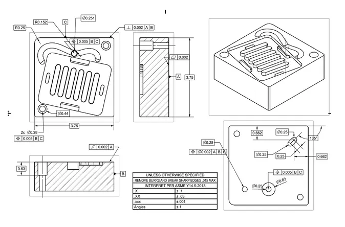
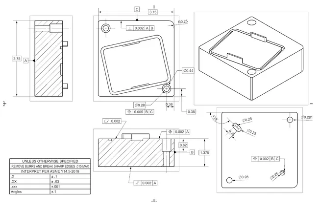
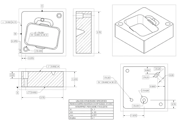
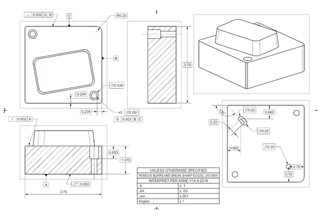
Appendix A: CAD Drawings of Parts
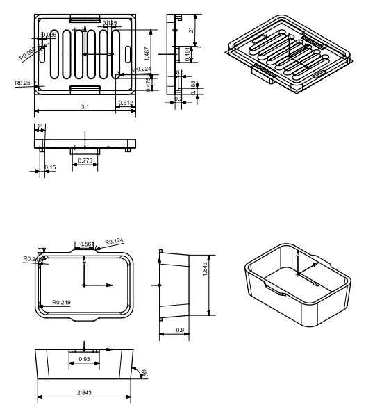
Appendix A: CAD Drawings of Parts