Table of Contents
Open Table of Contents
- Introduction
- Transmission Schematic and Design Description
- Overall Performance Metrics
- Geartrain and Gear Parameters
- Shaft Parameters
- Bearing Parameters
- Shaft 1 Assembly
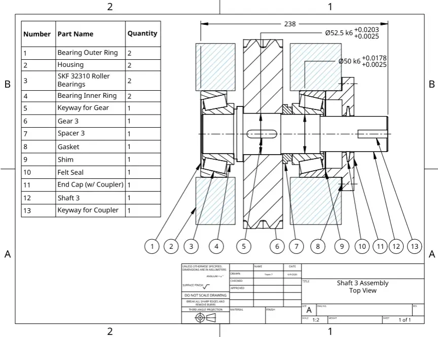
- Shaft 3 Assembly
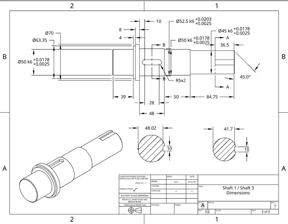
- Shafts 1 and 3 Part Drawing
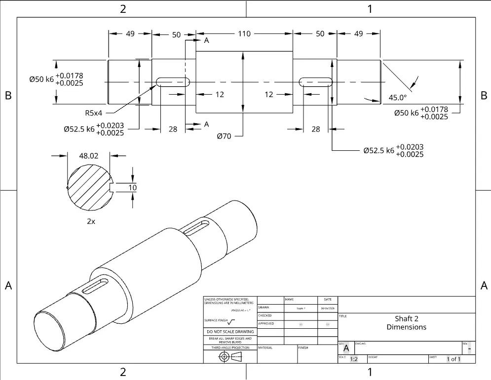
- Shaft 2 Part Drawing
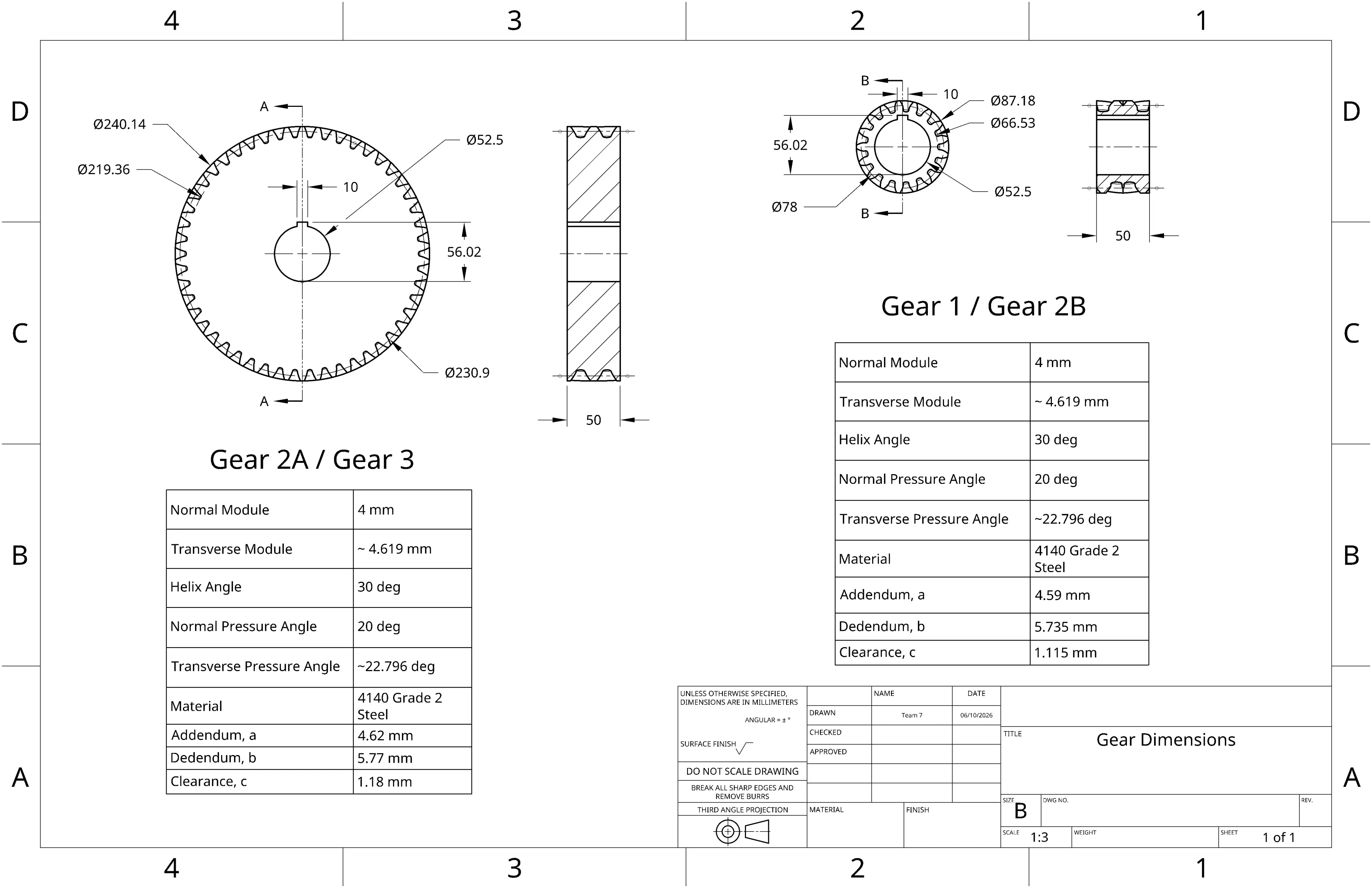
- Gears 1/2B & 2A/3 Part Drawings
- Appendix A: Shaft 1 Analysis
- Appendix B: Gear 1 Calculations
- Appendix B: Gear 1 Calculations
- Appendix C: Shaft 3 Analysis
- Appendix D: Gear 3 Calculations
- Appendix E: Bearing Calculations
Introduction
This past spring quarter at Northwestern, I took ME 315: Theory of Machines—Design of Elements, a fast-paced course covering fundamental mechanical components, failure theories, design criteria, and the structure of mechanical systems. The course focused on developing the skills needed to design and analyze basic machine elements and assemblies.
I had a great time in the class and especially enjoyed its rapid pace and breadth. It was a lot of material to absorb in just ten weeks, so and I definitely do not remember every equation or design rule off the top of my head. However, I thikn I came away with a strong foundation and the confidence to revisit and understand the material when needed.
For our final project, my partner, Nathan Shi, and I were tasked with designing a power transmission system that met the following specifications:
| Parameter | Value |
|---|---|
| Input power | |
| Input speed | |
| Required output speed | |
| Transmission type | Two-stage gear reduction |
| Number of shafts | Three shafts |
| Gear type | Spur or helical gears permitted |
| Minimum shaft diameter | |
| Operating schedule | 8 hours/day, 52 weeks/year |
| Required service life | Minimum 5 years |
| Reliability requirement | excluding bearings |
| Efficiency assumption | per gear mesh and bearings |
| Design objective | Compact, cost-effective design |
Other than that, we weren’t given much more guidelines (both fun and painful), which enabled us to be creative with our final design choice. We settled on a compact, two-stage reverted countershaft gearbox with coaxial input and output shafts. This (very late lol) post attempts to explain our design process.
Transmission Schematic and Design Description
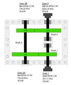
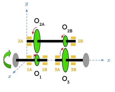
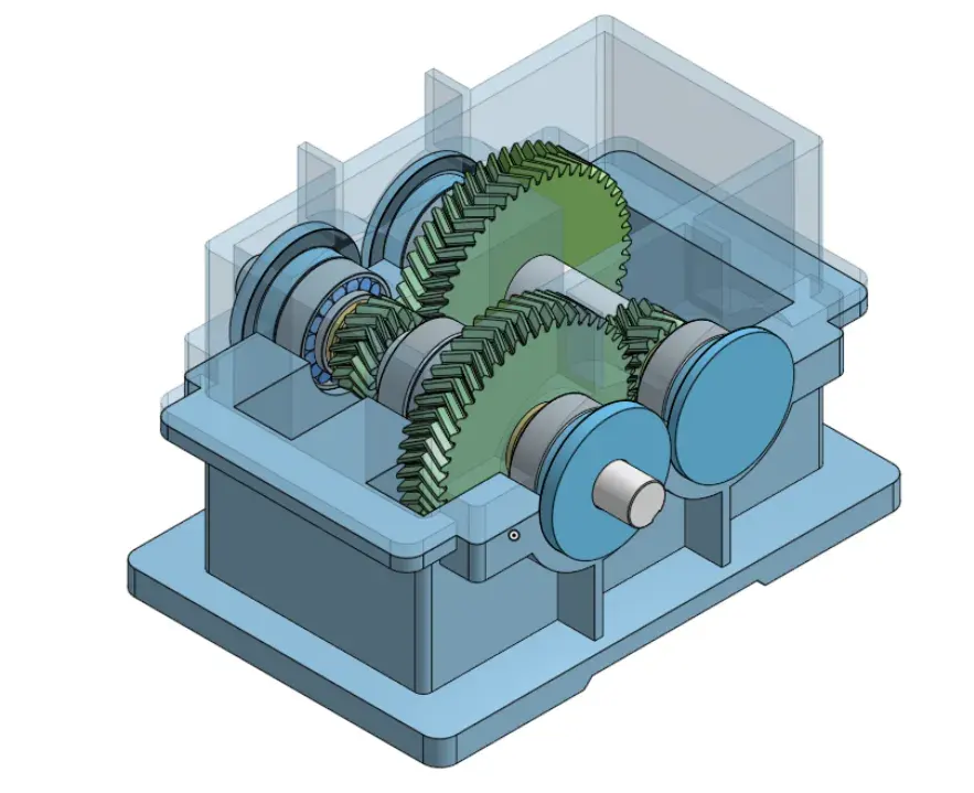
The final transmission design utilizes a compact reverted countershaft gearbox arrangement with a coaxial input and output configuration. Unlike a traditional parallel shaft gearbox, the selected layout minimizes the distance between the input and the output shafts by aligning them along the same centerline while maintaining independent shaft rotation. This reduces our footprint significantly.
In our configuration, the first-stage reduction occurs between shafts 1 and 2, and the second stage reduction occurs between shafts 2 and 3. This allowed us to make use of the principle of component standardization to reduce costs. Both gear stages utilize identical 17-tooth pinions and 50-tooth gears. The shafts were also intentionally designed with geometric similarity - shafts 1 and 3 share similar structural layouts bearing arrangements despite operating at different torque levels. This can help to simplify assembly, machining, and maintenance required while reducing the number of unique components.
The gearbox also utilizes herringbone gears rather than traditional spur or helical gears. Herringbone gears were selected because they have the smooth transmission and strong load capacity of helical gears while avoiding their pitfall of having axial loads. In traditional helical gear arrangements, axial loads require larger bearings that can handle these loads. However, by using opposite-hand helices within each herringbone, the axial forces generated by one helix are to be balanced by the other.
Overall Performance Metrics
| Performance Metric | Final Design Value |
|---|---|
| Input Power | 70 kW |
| Input Speed | 2600 rpm |
| Output Speed | 300.56 rpm |
| Required Output Speed Range | 300 ± 3 rpm |
| Overall Transmission Ratio | 8.651:1 |
| Transmission Error | 0.19% |
| Gear Type | Herringbone gears |
| Gear Material | AISI 4140 Grade 2 steel, 450 HB |
| Shaft Material | AISI 1045 steel |
| Number of Gear Stages | 2 |
| Gear Tooth Combination | 17:50 per stage |
| Center Distance per Stage | 154.73 mm |
| Overall Layout | Coaxial reverted countershaft gearbox |
| Net Axial Gear Force | Approximately 0 N |
| Minimum Gear Bending FoS | 1.90, Gear 2B |
| Minimum Gear Contact FoS | 1.35 |
| Minimum Shaft Static FoS | 2.14, Shaft 3 |
| Minimum Shaft Fatigue FoS | 1.92, Shaft 3 |
| Bearing Type Selected | SKF 32310 J tapered roller bearings |
| Maximum Required Bearing Rating | 194.24 kN |
| Selected Bearing Dynamic Rating | 211 kN |
| Bearing Maintenance Requirement | No bearing change service required |
| Expected Shaft Life | Infinite life, (N > 10^6) cycles |
| Critical Shaft | Shaft 2, due to highest moment and highest torque |
| Overall Limiting Design Factor | 1.35, gear contact safety factor |
Geartrain and Gear Parameters
| Item | Gear 1 | Gear 2A | Gear 2B | Gear 3 |
|---|---|---|---|---|
| Type | Herringbone | Herringbone | Herringbone | Herringbone |
| Teeth, (N) | 17 | 50 | 17 | 50 |
| Helix Angle (°) | 30 | 30 | 30 | 30 |
| Normal Module, (m_n) (mm) | 4 | 4 | 4 | 4 |
| Transverse Module, (m_t) (mm) | 4.6188 | 4.6188 | 4.6188 | 4.6188 |
| Pitch Diameter (mm) | 78.52 | 230.94 | 78.52 | 230.94 |
| Normal Pressure Angle (°) | 20 | 20 | 20 | 20 |
| Transverse Pressure Angle (°) | 22.80 | 22.80 | 22.80 | 22.80 |
| Face Width, (b) (mm) | 50.27 | 50.27 | 50.27 | 50.27 |
| Speed (rpm) | 2600 | 884 | 884 | 300.56 |
| Power (kW) | 70 | 70 | 70 | 70 |
| Total Torque (N·m) | 257.12 | 756.22 | 756.22 | 2224.18 |
| Tangential Force on Gear (N) | 6549.07 | 6549.07 | 19261.98 | 19261.98 |
| Radial Force on Gear (N) | 2752.42 | 2752.42 | 8095.36 | 8095.36 |
| Axial Force (N) | 0 | 0 | 0 | 0 |
| Material | 4140 G2 steel | 4140 G2 steel | 4140 G2 steel | 4140 G2 steel |
| Hardness (HB) | 450 | 450 | 450 | 450 |
| Hardness Ratio | 1.00 | 1.00 | 1.00 | 1.00 |
| Bending FoS | 5.58 | 7.52 | 1.90 | 2.56 |
| Contact FoS | 2.20 | 2.20 | 1.35 | 1.35 |
| Contact Ratio | 3.50 | 3.50 | 3.50 | 3.50 |
| Stage Transmission Ratio | 2.941 | 2.941 | 2.941 | 2.941 |
| Overall Transmission Ratio | 8.651 | 8.651 | 8.651 | 8.651 |
| Center Distance (mm) | 154.73 | 154.73 | 154.73 | 154.73 |
| Total Center Distance (mm) | 0, coaxial reverted layout | 0, coaxial reverted layout | 0, coaxial reverted layout | 0, coaxial reverted layout |
| Transmission Error | 0.19% | 0.19% | 0.19% | 0.19% |
Shaft Parameters
The number of cycles was calculated using , where hours. Since all shafts experience more than cycles, the shafts are treated as infinite-life fatigue components.
| Item | Shaft 1 | Shaft 2 | Shaft 3 |
|---|---|---|---|
| Material | AISI 1045 steel | AISI 1045 steel | AISI 1045 steel |
| Speed (rpm) | 2600 | 884 | 300.56 |
| Maximum Torque, (T) (N·m) | 257.12 | 756.22 | 2224.18 |
| Radial Bending Moment (N·m) | 75.87 | 386.29 | 223.16 |
| Tangential Bending Moment (N·m) | 180.53 | 771.96 | 530.98 |
| Maximum Bending Moment, (M) (N·m) | 195.83 | 863.21 | 575.97 |
| Minimum Diameter, (d_{\min}) (m) | 0.0200 | 0.0328 | 0.0287 |
| Minimum Diameter with Keyway (m) | 0.0210 | 0.0344 | 0.0301 |
| Number of Cycles (million cycles) | 1622.4 | 551.6 | 187.5 |
| Location of Critical Cross Section | Center of Gear 1 | Center of Gears 2A/2B | Center of Gear 3 |
| Static FoS | 14.77 | Not calculated | 2.14 |
| Fatigue FoS | 8.20 | Not calculated | 1.92 |
| Expected Life | Infinite | Infinite | Infinite |
Bearing Parameters
| Item | Bearings 1A & 1B | Bearings 2A & 2B | Bearings 3A & 3B |
|---|---|---|---|
| Radial Force on Bearing (N) | 1376.21 | 3841.28 / 7006.50 | 4047.68 |
| Tangential Force on Bearing (N) | 3274.54 | -1288.92 / 14001.83 | 9630.99 |
| Total Bearing Load (N) | 3551.98 | 4051.76 / 15657.02 | 10446.99 |
| Required Dynamic Rating, (C) (N) | 63136.31 | 50266.57 / 194242.52 | 90459.24 |
| SKF Bearing Number | 32310 J | 32310 J | 32310 J |
| Bore Diameter (mm) | 50 | 50 | 50 |
| Width (mm) | 42.25 | 42.25 | 42.25 |
| Dynamic Load Rating, (C_1) (kN) | 211 | 211 | 211 |
| Outside Diameter (mm) | 110 | 110 | 110 |
| Expected Life (million cycles) | 1622.4 | 551.6 | 187.5 |
| Bearing Change Services | Not needed | Not needed | Not needed |
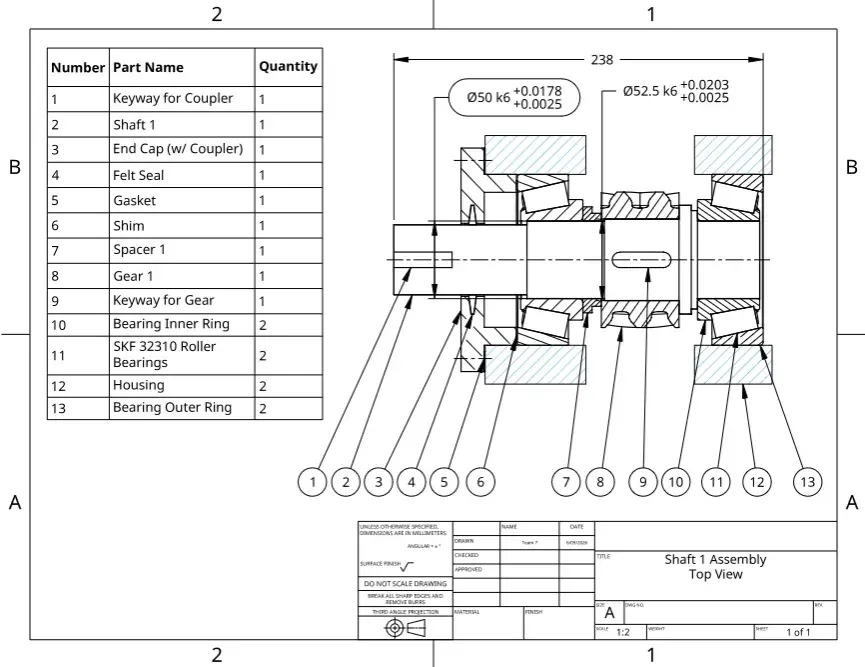
Shaft 1 Assembly
Shaft 3 Assembly
Shafts 1 and 3 Part Drawing
Shaft 2 Part Drawing
Gears 1/2B & 2A/3 Part Drawings
Appendix A: Shaft 1 Analysis
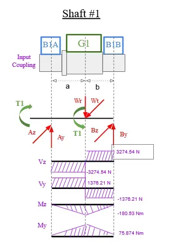
Given Values
, , , , , , and .
Bearing Reactions
Resultant Bearing Forces
Maximum Bending Moments
Minimum Shaft Diameter
Keyway Correction
Bending and Torsional Stresses
Due to the required load bearing and subsequent size of the bearings, a diameter of 52.5 mm was chosen at the location of the highest stress and moment. Using:
Von Mises Stresses
Static FoS
Fatigue Analysis
The fatigue life of Shaft 1 was checked using the modified Goodman relation. Since the shaft rotates while the transverse gear load remains fixed in space, the bending stress is treated as fully reversed. The transmitted torque is treated as steady.
The shaft material is AISI 1045 steel with:
The uncorrected endurance limit for steel is estimated as:
The corrected endurance limit is:
The surface finish factor for machined steel is:
Using machined surface constants:
The size factor is:
Using:
The load factor for bending is:
The temperature factor is:
The reliability factor for 99% reliability is:
Therefore:
Using the previously calculated Shaft 1 stresses:
The equivalent alternating stress is:
The equivalent mean stress due to steady torsion is:
The modified Goodman fatigue criterion is:
Since:
Shaft 1 satisfies the fatigue requirement. Since the cycle count exceeds , Shaft 1 is treated as an infinite-life shaft.
Appendix B: Gear 1 Calculations
Input Requirements
The gearbox input conditions were specified by the project requirements as:
The desired output speed was:
This required an overall transmission ratio near:
Transmission Ratio Selection
A two-stage reduction was selected to avoid excessively large gears and maintain a compact gearbox design. The selected tooth combination was:
for both stages. This produced:
and therefore:
This satisfies the required output-speed range.
Helix Angle
A helix angle of:
was selected because larger helix angles improve tooth overlap and transmission smoothness while remaining manufacturable.
Gear Module and Pitch Diameter
A normal module of:
was selected. A smaller module would reduce gearbox size but significantly increase tooth stress, while a larger module would unnecessarily increase the gear size and center distance.
The transverse module is:
The pitch diameter of Gear 1 is:
Pressure Angles
A standard normal pressure angle of:
was selected because it provides a good balance between bending strength, contact stress, and manufacturability.
The transverse pressure angle becomes:
Gear Forces
The tangential gear force was calculated from:
The radial force was calculated using the transverse pressure angle:
Since herringbone gears were selected, the net axial force is approximately zero.
Face Width
The face width was selected using a helical-gear overlap estimate:
The selected face width improves tooth-load distribution and reduces local bending stress.
Gear Material Selection
AISI 4140 Grade 2 steel was selected for all gears because of its high strength, good fatigue resistance, and suitability for high-power gearbox applications.
The smaller 17-tooth pinions experience the highest bending stresses because of their lower tooth counts and smaller pitch diameters. Using a higher-strength alloy steel improves reliability under long-term cyclic loading.
Appendix B: Gear 1 Calculations
Input Requirements
The gearbox input conditions were specified by the project requirements as:
The desired output speed was:
This required an overall transmission ratio near:
Transmission Ratio Selection
A two-stage reduction was selected to avoid excessively large gears and maintain a compact gearbox design. The selected tooth combination was:
for both stages. This produced:
and therefore:
This satisfies the required output-speed range.
Helix Angle
A helix angle of:
was selected because larger helix angles improve tooth overlap and transmission smoothness while remaining manufacturable.
Gear Module and Pitch Diameter
A normal module of:
was selected. A smaller module would reduce gearbox size but significantly increase tooth stress, while a larger module would unnecessarily increase the gear size and center distance.
The transverse module is:
The pitch diameter of Gear 1 is:
Pressure Angles
A standard normal pressure angle of:
was selected because it provides a good balance between bending strength, contact stress, and manufacturability.
The transverse pressure angle becomes:
Gear Forces
The tangential gear force was calculated from:
The radial force was calculated using the transverse pressure angle:
Since herringbone gears were selected, the net axial force is approximately zero.
Face Width
The face width was selected using a helical-gear overlap estimate:
The selected face width improves tooth-load distribution and reduces local bending stress.
Gear Material Selection
AISI 4140 Grade 2 steel was selected for all gears because of its high strength, good fatigue resistance, and suitability for high-power gearbox applications.
The smaller 17-tooth pinions experience the highest bending stresses because of their reduced tooth counts and smaller pitch diameters. Using a higher-strength alloy steel improves reliability under long-term cyclic loading.
Appendix C: Shaft 3 Analysis
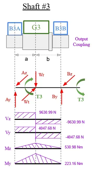
Given Values
For Shaft 3, the input values are:
The gear is centered between the bearings, so:
Bearing Reactions
Gear 3 is positioned between Bearings 3A and 3B. Since the gear is centered between the bearings in the simplified model, the bearing reactions are equal.
For the radial-force plane:
For the tangential-force plane:
The resultant bearing force is:
Shear Force and Bending Moment
The shear-force diagrams are drawn separately in the radial and tangential planes.
For the radial-force plane:
from Bearing 3A to Gear 3. At Gear 3:
from Gear 3 to Bearing 3B.
For the tangential-force plane:
from Bearing 3A to Gear 3. At Gear 3:
from Gear 3 to Bearing 3B.
The bending-moment diagrams are triangular, with the maximum bending moment occurring at Gear 3. From the force diagram:
The resultant maximum bending moment is:
Minimum Shaft Diameter
The shaft is checked under combined bending and torsion. The equivalent moment is:
Using:
the theoretical minimum shaft diameter is:
A keyway correction factor of 1.05 is applied:
However, this value is only a theoretical lower bound. Since Shaft 3 carries the largest torque and must support the output coupling, bearing seats, shoulders, and keyways, the final minimum design diameter was selected as:
Static Stress Analysis
Using:
the bending stress is:
The torsional shear stress is:
The von Mises stress is:
Using AISI 1045 steel with:
the static factor of safety is:
Fatigue Analysis
The operating-life requirement is:
The number of cycles is:
Since:
Shaft 3 is treated as an infinite-life fatigue shaft.
The alternating and mean stress components are:
The material ultimate tensile strength is:
The uncorrected endurance limit is:
The corrected endurance limit and fatigue factor of safety are found using the Marin factors and modified Goodman criterion:
The equivalent alternating stress is:
The equivalent mean stress is:
The modified Goodman fatigue criterion is:
Therefore, Shaft 3 satisfies the fatigue requirement. Since it carries the highest torque, Shaft 3 is the most critical output shaft, but the selected diameter of provides an acceptable fatigue factor of safety.
Appendix D: Gear 3 Calculations
Gear 3 is the final output gear mounted on Shaft 3, so it carries the highest torque in the gearbox. The selected gear parameters are , , , , , and .
Transmission Ratio
Transverse Module and Pitch Diameter
Transverse Pressure Angle
Torque and Gear Forces
Since Gear 3 is a herringbone gear, the axial forces from the two opposite helix directions cancel in the shaft direction:
Face Width
The selected face width is based on the helical-overlap estimate:
Therefore, the selected face width is:
Bending Stress and Factor of Safety
Using the Lewis bending equation with for the 50-tooth gear:
Using an allowable bending stress of , the bending factor of safety is:
Center Distance
The second-stage center distance is:
Appendix E: Bearing Calculations
The same SKF 32310 J bearing was selected for all bearing locations to simplify part standardization. The required dynamic load rating was checked using:
where is the bearing load in kN and:
Shaft 1 Bearings
Shaft 3 Bearings
Shaft 2 Critical Bearing
The largest required bearing rating is therefore:
The selected SKF 32310 J bearing has:
Since:
the selected bearing satisfies the required dynamic load rating for every bearing location in the gearbox. Therefore, the same bearing can be used throughout the design, and no bearing-change service is required.