Table of Contents
Open Table of Contents
Introduction
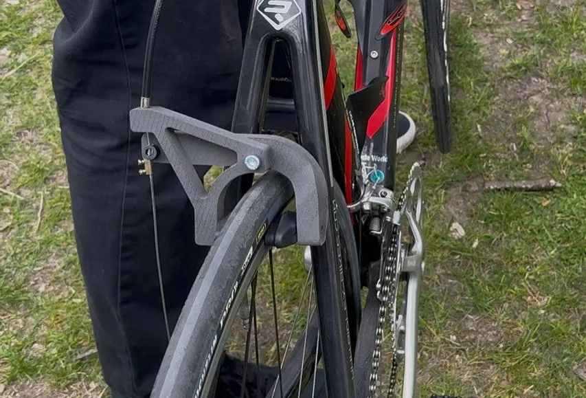
I’ve put this post off for long enough! Last spring, I took ME240 (Introduction to Mechanical Design and Manufacturing), as part of a required sequence for undergrad mechancical engineers. While the course was not my first exposure to manufacturing, I appreciated the formal structure the class placed on mechanical design, especially at scale. Most of my previous experiences emphasized ‘scrappiness’. That is, getting a ‘first-order’ approximation of the final product out of the way, then iterate. However, the structure of ME240 placed significant weight on the evidence behind design desicions, which I appreciated. Over 10 weeks, my team members and I designed and verified functional brake calipers for the rear wheel of a bicycle. This post will explain how!
Needs and Metrics
Our needs listed in Table 2 were generated through a combination of rider experience, engineering judgment, and alignment with ISO 4210-4 bicycle safety standards. High-priority needs (e.g., stopping distance, ease of brake actuation, structural rigidity) directly impact rider safety and brake performance. Lower-priority needs, such as aesthetically pleasing, still contribute to usability and product desirability but are less critical to core function.
Metrics in Table 3 were derived to evaluate how well each design met the needs. Each metric corresponds to one or more needs and was selected due to ease of measurability with available tools (such as a stopwatch, tape measure, scale, camera). Thresholds for marginal and ideal values were informed by ISO standards where applicable, past design benchmarks, and practical engineering limits. For example, our braking distance goal was informed by ISO 4210-4, which specifies stopping performance. Weight was targeted based on component strength tradeoffs. Force on the brake handle was capped at 100 N for ideal use, and qualitative metrics such as aesthetics were captured by Likert scales. Installation time was included to address usability.
This systematic development of needs and standards allow us the confidence that our caliper’s results are representative of use in the real world.
Needs
| # | Need | Priority (1–5) |
|---|---|---|
| 1 | Design is lightweight | 4 |
| 2 | Stopping distance minimized | 5 |
| 3 | Handle is easy to depress | 5 |
| 4 | Allows braking sensitivity adjustment | 4 |
| 5 | Durable after repeated use | 4 |
| 6 | Easily replaced/maintained | 1 |
| 7 | Aesthetically pleasing | 2 |
| 8 | Ease of manufacturing | 2 |
| 9 | Smooth braking | 3 |
| 10 | Environmental impact | 1 |
| 11 | Withstands the elements | 4 |
| 12 | Compatible with given mounting | 5 |
| 13 | Affordable | 2 |
| 14 | Doesn’t affect other parts of the bike | 5 |
| 15 | Easy installation | 1 |
| 16 | Remains rigid under hard braking | 5 |
| 17 | Consistent braking behavior in different environments | 4 |
| 18 | Compliant with all relevant engineering standards | 5 |
| 19 | Reduces noise of braking | 2 |
Metrics
| Metric | Marginal | Ideal | Measured (Lab 8) | Measured (Lab 10) | Units | Measurement Tool |
|---|---|---|---|---|---|---|
| Weight (combined calipers) | 400 g | 200 g | 79 g | 64.7 g | grams | Spring scale |
| Braking distance | 15 m | 4.572 m | 10.135 m | 12.8 m | meters | Measuring tape |
| Aesthetically pleasing | 1 | 5 | 5 | 5 | 1–5 scale | User feedback |
| Smooth braking | No | Yes | Not checked | Yes | Binary | Rider observation |
| Deformation under hard braking | 0 mm | 5 mm | 4 mm avg | ~6 mm | mm | Measuring tape |
| Force on hand brake lever | 450 N | 100 N | 95 N | 95 N | Newtons | Spring scale / force gauge |
| Time to install brake calipers | 30 min | 10 min | 3.3 min | ~4 min | minutes | Stopwatch |
| Components loosen/displace | Yes | No | No | No | Binary | Visual inspection |
| Stop time variance (avg of 2 stops) | ±1.5 s | ±0.5 s | ±1.46 s | ±5.6 s | seconds | Stopwatch + averaging |
Design Concept Development
To generate initial concepts for our custom brake calipers, we followed the tried and true engineering design process combining estimation, simulation, and iteration. Our goal was to minimize caliper weight while ensuring sufficient strength, stiffness, deflection control, and aesthetics to meet the ISO 4210-4 safety and performance criteria.
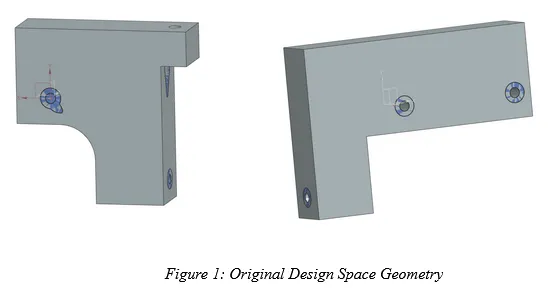
We first estimated the geometric bounds of the caliper design space by using dimensions provided by our instructor. These dimensions referenced standard caliper geometries and measuring clearances around the bike rim and fork. This informed the allowable geometric constraints for our designs, which we later refined through CAD and fitting with prototype 1.
We also developed multiple concept sketches to explore configurations of caliper geometries. Particularly, we focused on limiting stress concentrations by avoiding sharp corners or turns in our geometry. Sketches emphasized load path clarity and mounting point access.
Next, by using static force diagrams and hand calculations, we modeled the braking forces transmitted from the cable and then to the caliper frame. We estimated typical tension forces up to 200 N in the cable and reaction forces were found to be ~140 N shear, 200 N normal, per pad. Based on these loads, we iterated upon our sketches to prioritize geometries that enable a direct force transfer along stiff paths to minimize bending. We also calculated an initial allowable stress target of 43 MPa based on estimated operational stresses and a safety factor of 0.604 (derived from 32 MPa max operational / 53 MPa allowable).
Through the analysis of material property charts, containing information regarding specific strength, toughness, and corrosion resistance, we identified titanium alloys as the optimal candidate. However, due to availability and manufacturing constraints, we used Nylon 12, a polymer with a high toughness and acceptable fatigue resistance, which is suitable for 3D printing.
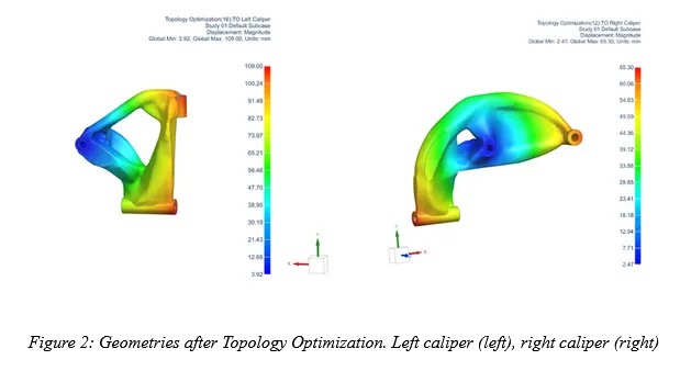
We used topology optimization to inform us in ways we could reduce mass while maintaining structural integrity under realistic loading conditions. Applied loads included 200N tension at cable, 140 N shear at brake pad, 200 N normal to brake pad, and a mass constraint of 7.45 grams (based on ¼ of 29.8 target mass). Optimization revealed that some material could be removed from lower stress regions near the center of the design space. We used pockets and fillets to reduce stress concentrations which improved stiffness-to-weight ratio and also enhanced fatigue life by potentially stopping cracks from propagating
We iteratively refined our geometry using FEA (Finite Element Analysis) to evaluate von Mises stress and displacement under loads. Localized high stress values were determined to be numerical errors in loading/constraint locations. Elsewhere, our design ensured stresses remained within allowable limits, confirming integrity.
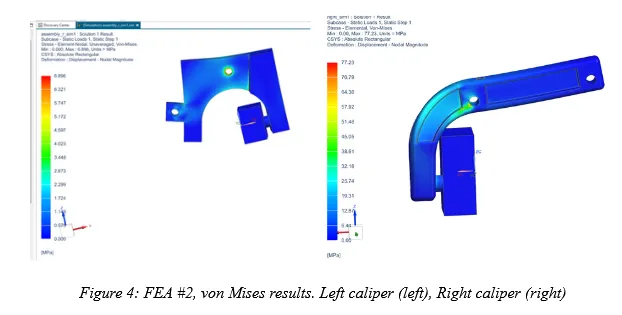
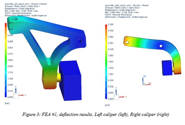
Our stress SF was 53 MPa / 32 MPa ~ 1.66. We found that our displacements were less than 11mm, so we decided that we did not need a formal safety factor. Our yield and fatigue margin is based on 50,000 use cycle assumptions and nylon-12 polymer behavior.
Initial Testing Results
| Metrics | Measured | Units | Measurement Tool |
|---|---|---|---|
| Mass | 29 (L), 50 (R), 79 (total) | grams | Scale |
| Braking distance | 10.6 (test 1), 9.67 (test 2) | meters | Measuring tape |
| Aesthetically pleasing | 5 | 1–5 | Likert Scale |
| Smooth braking | No (significant skidding) | Binary | Rider |
| Deformation under hard braking | ~4 | mm | Measuring tape |
| Force on hand brake lever | 95 | Newtons | Spring scale / Force gauge |
| Time to install brake calipers | ~3 | Minutes | Stopwatch |
| Brake components loosen/displace | No | Binary | Visual inspection |
| Repeated stop time variance (avg of 2) | 1.46 | Seconds | Stopwatch + averaging |
In anticipation of the tolerance associated with SLS printing Nylon-12, our team increased the diameter of each caliper’s central pivot hole by 0.1 mm before printing. However, during testing the pivot holes were still too small for easy pivoting around the mounting screw. As a result, a ¼’’ drill bit was used to provide more clearance. The size of the brake pad attachment holes were perfect, allowing a secured, screwed fit.
Besides the issues mentioned above, there were no major issues with assembly or attachment. After assembly, the calipers slid past each other smoothly and the brake pads aligned properly with the rim without restricting it during regular riding.
Our most important takeaway from the tests was the braking distance of the rear calipers. The adjusted stopping distances were significantly below the ISO 4210-4 standard of 15 m (see Table 4). Significant wheel skidding was also observed in both tests. Additionally, the right caliper was very heavy when measured on a scale. All of these observations indicated that the calipers were too strong and overdesigned.
Design Improvements
We largely kept our calipers the same between our initial design and final design. Our initial design was quite successful, with a calculated stopping distance of around 10 m at 25 km/h, and therefore we had some room to reduce the design’s weight (and therefore material cost) while still staying within the limits of ISO 4210-4.
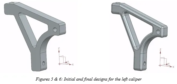
For the left caliper, only slight changes were made, including increased use of edge blending in order to slightly reduce weight while also providing smoother changes in geometry to increase strength. These blends also gave the part a sleeker appearance and more aesthetic appeal.
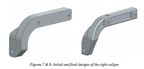
More work was done on the right caliper before our final tests, as it was significantly heavier than the left caliper in our initial design and had far more room for improvement as far as weight reduction. We introduced cutout portions on the extended arm of the caliper which formed an I-beam-like cross section, reducing weight significantly while maintaining strength in the plane in which the calipers will deflect. Chamfers used on the brake pad attachment area were also increased in size to take more material off of the part while maintaining general shape and dimensionality. As with the left caliper, edges were also smoothed out more extensively in order to minimize sharp geometrical changes and slightly reduce weight, while also providing a more sleek and professional look.
Final Testing Results
| Metrics | Measured | Units | Measurement Tool |
|---|---|---|---|
| Mass | 36.7 (R) + 28 (L), 64.7 (total) | grams | Scale |
| Braking distance | 12.8 | meters | Measuring tape |
| Aesthetically pleasing | 5 | 1–5 | Likert Scale |
| Smooth braking | Yes (minimal skidding, clean stop — shown from longer stop time) | Binary | Rider |
| Deformation under hard braking | ~6 | mm | Measuring tape |
| Force on hand brake lever | 95 | Newtons | Spring scale / Force gauge |
| Time to install brake calipers | ~4 | Minutes | Stopwatch |
| Brake components loosen/displace | No | Binary | Visual inspection |
| Repeated stop time variance (avg of 2) | 5.6 | Seconds | Stopwatch + averaging |
The main insight that we gathered from our second and final round of testing was realizing just how much we could have altered the calipers and stayed within the limitations of the ISO standard. Given the changes that we made to calipers’ total weight, a measured reduction of almost 15 grams, we were expecting a more significant increase in stopping distance, but this was not the case. Since we were left with more than 2 meters of clearance between our stopping distance and the standard, more material could have been removed from the calipers while still meeting our established requirements.
As far as our initial needs and metrics, nearly all of our needs were met at at least a marginal level, with some even exceeding our chosen ideal specifications. This suggests that perhaps our ideal values were too easily attainable, and that our estimations were not appropriate due to a lack of prior testing data. Our key metrics – weight, braking distance, deformation, and braking force – were all successfully met, some of which also exceeded our ideal estimations.
Additional Improvements & Manufacturability
The adjusted stopping distance from the improved design (see Table 5) is still reasonably below the ISO 4210-4 given standard (15 m). As a result, the calipers can be reduced in weight further to ensure riders are not carrying around too much weight.
For scenario A, because of the necessity for dimensional accuracy at certain points, we recommend forging (specifically closed die). While the upfront cost of closed die forging is high, the high volume of production reduces this cost in the long run. Forging also produces an acceptable finish. Casting does not provide the dimensional accuracy required for the precision mounting holes. Machining produces too much material waste and is not suited for high volume production. Forming is also not ideal because resulting springback affects precision and parts are limited to uniform thickness.
For scenario B, we recommend CNC machining because of the focus on a premium finish and strength. Because CNC machining is subtractive, there is maximum control over the surface finish. The resultant parts are also high strength because of the stock material that is used. The high cost of CNC machining is compensated by the lower production volume and the higher target price. Forging and additive manufacturing both have surface finishing worse than CNC machining.
For scenario C, we recommend additive manufacturing because of the focus on fast design iteration, low tooling cost, and flexibility. No other manufacturing method comes close to additive manufacturing in terms of its potential for iterative design that can be changed at little to no cost. CNC machining produces a high tooling cost compared to additive manufacturing.
Discussion
The design process for creating the brake calipers was very insightful, and overall, our group learned a lot about prototyping, testing, and applying performance standards. Initially, it was a bit challenging to navigate through the ANSI website and find relevant specifications that related to our specific design requirements. Also, conducting research and compiling metrics in the beginning stages of designing was a bit difficult; it was hard to gauge what data we would need later on. However, once we started prototyping our design and familiarizing ourselves with CAD labs, we were able to see how the metrics we found earlier fit in smoothly with the design process.
Overall, communicating clearly in and out of labs, and having time allotted specifically for optimizing our design helped us in the long run. By spending more time on our first iteration– ensuring that we optimized weight, geometry, and stress distributions– testing and future iterations became a lot easier. For example, after our initial test, we only had to focus on small adjustments such as weight reduction because we had already spent time optimizing geometry and stresses.